Rhino, Revit and Shared Coordinates: keep coordination simple with BEAM
- Mauro Sabiu
- Apr 14
- 4 min read
Shared Coordinates, Internal Origin, and Better Rhino–Revit Workflows
Location and coordinates are fundamental to every architectural or engineering model. They define where the project sits in space and how it relates to the real world.
To work efficiently, it helps to understand that a model usually involves two different coordinate concepts:
1. Internal Origin
Every CAD or BIM platform has one true geometric coordinate system used internally by the software.This is the system where all geometry is calculated using XYZ values from a single point: (0,0,0).
That point is often called the Internal Origin.
All objects in the model are mathematically defined relative to this origin. It is the coordinate system the software uses for calculations, geometry operations, snapping, scripts, exports, and precision.
There is only one internal geometric origin.
2. Shared Coordinates / World Coordinates
Projects also need to relate to the real world.
For that reason, software allows an additional coordinate reference system that defines how the internal model relates to site coordinates, survey data, GIS references, consultant files, or national grid systems.
This is commonly called:
Shared Coordinates in Autodesk Revit
Survey coordinates
World Coordinate System (WCS) in some CAD tools
This system typically stores:
Easting / Northing / Elevation
Rotation to North
Relationship between the model and real-world location
So rather than moving the building geometry to huge real-world coordinates, the model stays clean internally while another coordinate system defines where it belongs externally.
Shared Coordinates are simply offset and rotation values applied to the model’s local geometry coordinates to represent real-world position, keeping the actual geometry near the origin and therefore more stable and precise.
Why This Matters
A common mistake is placing project geometry directly at real-world coordinates.
For example, if the site coordinate is hundreds of thousands of metres from zero, the building may also be modelled there.
That creates problems because computers have limited numerical precision. When coordinate values become very large it will truncate values:
curves may fail
surfaces may contain tiny gaps
modelling commands become unstable
interoperability becomes unreliable
scripts may fail
display artifacts appear
This is especially noticeable in Rhino and other geometry-heavy workflows.
Our Recommendation
Never model in real-world coordinates. Keep the actual model geometry close to the internal origin. Use shared coordinates only as a reference layer between the model and the real world.
Best Practice for Project Setup
A practical workflow is:
Internal Origin
Place it in a logical modelling location, often near the project extents, such as a bottom-left corner outside the building footprint.
Benefits:
coordinates remain small and positive
geometry stays stable
future project expansion does not cross axes
modelling remains efficient
Shared Coordinates
Then define a survey point or shared coordinate system that says:
This real-world point is located here relative to the model.
If later the project moves 1 metre east, you usually adjust the shared coordinates instead of moving the whole building.
That keeps the geometry untouched and coordination simple.


Revit and Rhino Comparison
In Revit
Autodesk Revit includes:
Internal Origin
Survey Point / Shared Coordinates
Project Base Point (useful in some workflows, though often secondary)
In Rhino
Rhino uses:
World Top CPlane as the internal modelling origin
Named CPlanes as alternate coordinate systems
So in practice, a Named CPlane can represent shared coordinates.
Our Recommended Rhino–Revit Workflow
For daily modelling, we usually recommend:
Internal Origin → Internal Origin
Keep Rhino and Revit aligned using their internal modelling origins.
This gives stable files, cleaner geometry and easier exports/imports with fewer precision issue
But What If Shared Coordinates Are Required?
Sometimes projects are already established differently for various reasons:
consultant models use site coordinates
IFC files come from another internal origin
project setup is already fixed
multiple disciplines must align via survey coordinates
In those cases, shared coordinates still matter.
Existing Solution in BEAM
BEAM and RAY already support shared-coordinate workflows.
In Rhino, users could create a Named CPlane matching the Revit shared coordinate system, allowing proper alignment while modelling near origin.
This works well, but it requires manual setup and deeper coordinate knowledge.
New Improved Workflow
With version 1.14.4.2, BEAM extends this further with improved Revit → Rhino Shared Coordinates support, making coordination much easier while keeping modelling workflows clean.
How it works
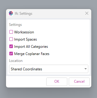
In Revit, use RAY to export the model using Shared Coordinates.
In Rhino, use RAY to import that coordinate system as a Named CPlane.
When importing IFC files, consultant models, or external geometry, select that Named CPlane so incoming files land in the correct shared position.
Once coordination is complete, continue working in Rhino with normal local modelling coordinates close to origin, where performance and precision are best.
When geometry is sent back to Autodesk Revit through BEAM, the shared coordinate relationship is preserved.
The Result
You get the best of both systems:
accurate coordination with consultants and IFC data
stable Rhino files near origin
easier navigation and cleaner modelling
fewer precision issues
no manual moving or guessing rotations
In short, you can coordinate in shared coordinates while continuing to design in local coordinates.


Comments